
Views: 0 Author: Site Editor Publish Time: 2026-08-20 Origin: Site


The loading and unloading phase is the most dangerous part of bulk liquid transport. Moving thousands of gallons of highly flammable product between storage racks and transport vehicles creates a high-risk environment. A single mechanical failure or procedural oversight can trigger hazardous spills, vapor ignitions, or static discharges. Fleet operators and procurement managers face a saturated market of safety components. Over-specifying adds unnecessary weight and reduces payload capacity. Under-specifying risks DOT non-compliance, catastrophic equipment failure, and massive liability exposure. Evaluating a modern Fuel Tanker Trailer requires moving beyond basic capacity metrics. You must scrutinize the specific engineering of its transfer and safety systems. This guide provides a technical framework for specifying the right loading and unloading components to ensure maximum risk mitigation and operational efficiency during every transfer.
Bottom Loading is the Standard: Bottom loading systems drastically reduce liquid turbulence, static buildup, and operator fall risks compared to legacy top-loading methods.
Interlocked Safety is Non-Negotiable: Modern trailers require integrated pneumatic and electronic interlocks (brakes, grounding, overfill) to remove human error from the transfer process.
Vapor Recovery Drives Compliance: Efficient vapor recovery systems are mandatory for environmental compliance and site safety, particularly when configuring an aluminum gasoline tank trailer.
Material and Payload Dictate System Specs: The specific gravity, viscosity, and volatility of the payload (e.g., diesel vs. aviation fuel vs. gasoline) dictate the necessary valving, pump configurations, and sensor types.
Bulk transfer operations must balance rapid transfer rates with absolute risk mitigation. Terminals demand fast turnaround times. Pushing petroleum products at 600 gallons per minute (GPM) increases the physical forces acting on the equipment. You have to move maximum volume without blowing out seals, causing pipe cavitation, or bypassing safety interlocks. The structural integrity of the safety systems must withstand these daily pressure cycles.
The Department of Transportation establishes the regulatory framework through DOT 406 specifications. This standard governs the construction and operation of petroleum transport vehicles. It mandates specific requirements for tank shell thickness, rollover protection, and emergency venting. Compliance is the minimum threshold for operation, not the ceiling for safety. Forward-thinking fleets specify systems that exceed these baseline requirements to build a wider margin of error.
Transfer operations face three primary risk vectors. You must engineer mechanical and procedural solutions to address each one directly:
Static Electricity Discharge: Hydrocarbons are poor conductors of electricity. Flowing fuel generates a static charge that accumulates on the metal chassis and sparks if not properly dissipated to the earth.
Vapor Ignition: Displaced air inside the tank contains highly flammable vapors. If these vapors escape near an ignition source or a static spark, a flash fire occurs instantly.
Mechanical or Operator-Induced Overfills: Pumping fuel past the tank's maximum capacity causes structural stress, blown pressure vents, and severe environmental contamination.
Safety Metric | DOT 406 Minimum Requirement | Fleet Best Practice Specification |
|---|---|---|
Overfill Protection | Basic mechanical or single-sensor electronic | Redundant 5-wire optic sensors with pneumatic backup |
Vapor Recovery | Standard venting to atmosphere (where legal) | Closed-loop sequential pneumatic vapor recovery manifold |
Emergency Valves | Internal mechanical valves | Air-operated internal valves with shear grooves |
Brake Interlocks | Not universally mandated | Fully integrated pneumatic drive-away protection |
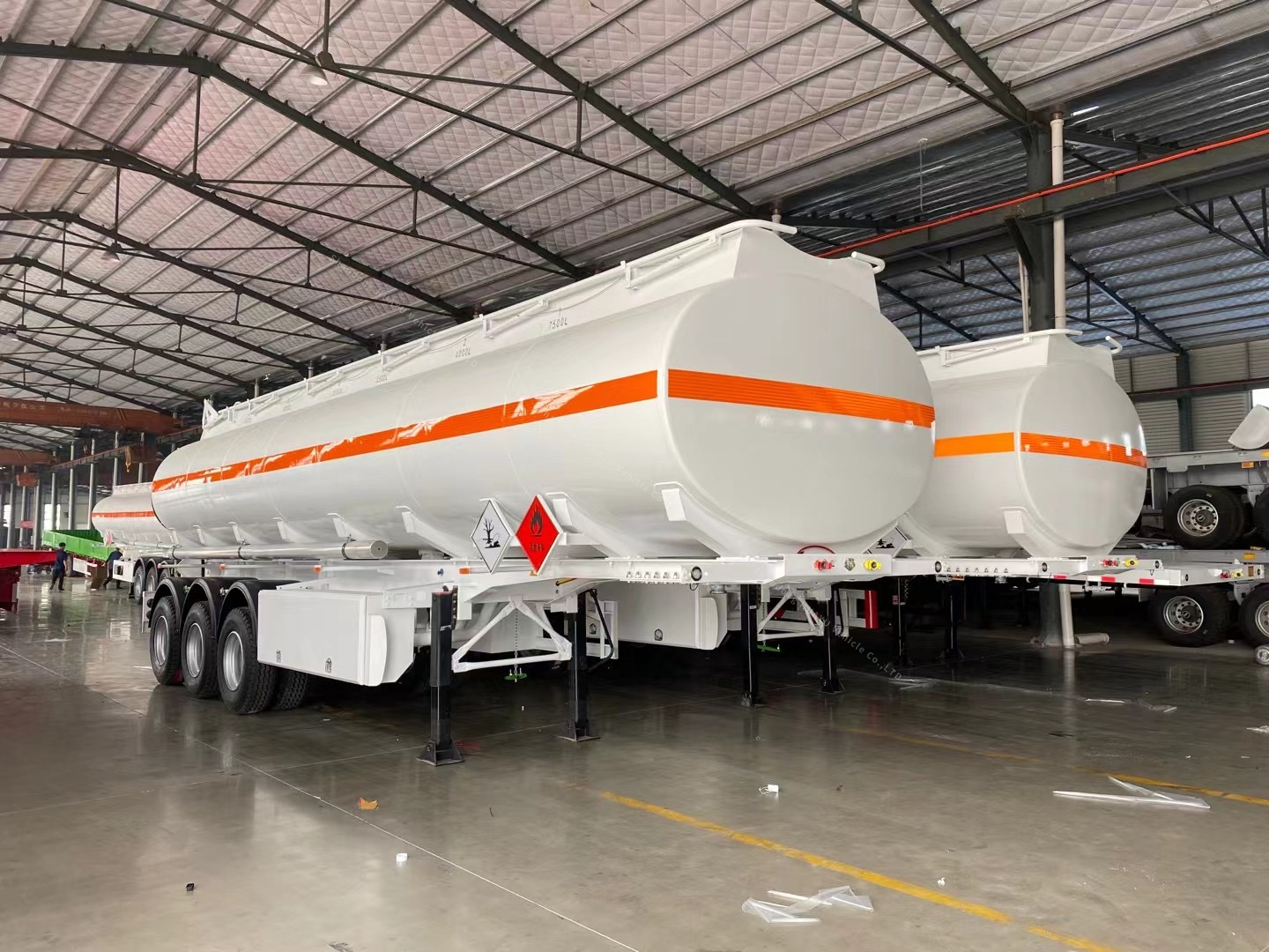
The industry has fundamentally shifted away from top loading. Bottom loading is the definitive choice for modern fleets. This method utilizes API (American Petroleum Institute) adapters located at the bottom of the tank shell. Operators connect loading arms directly to these adapters while standing safely on the ground. The fuel enters the compartment from the bottom, filling upwards.
This structural shift directly impacts fluid dynamics. Top loading drops fuel from above, causing massive liquid agitation. This turbulence generates high levels of static electricity and accelerates the release of flammable vapors. Bottom loading introduces the liquid smoothly. It limits turbulence, keeps the product stable, and drastically reduces the generation of static and vapors. This physical change directly prevents flash fires.
Operator safety drives this transition. Top loading requires personnel to climb atop the trailer, walk along narrow walkways, and handle heavy hoses at height. This introduces severe slip-and-fall liabilities, especially in rain, snow, or ice. Bottom loading eliminates this requirement entirely. Operators remain on the ground, connecting hoses and monitoring systems from a secure, accessible position.
The standard bottom loading sequence removes guesswork and enforces a linear safety protocol:
The driver spots the trailer at the loading rack and sets the parking brakes.
The driver connects the grounding and bonding cable to the trailer's verification plug.
The driver connects the vapor recovery hose to the trailer's vapor manifold.
The driver connects the API loading arms to the corresponding bottom adapters.
The driver opens the internal emergency valves via the pneumatic control block.
The terminal automation system verifies ground and overfill status before initiating pump flow.
Overfill protection systems act as the primary defense against spills. These systems utilize sensors mounted inside the tank compartments. When the liquid reaches a predetermined maximum level, the sensor sends a signal to the terminal loading rack. The rack's automated systems immediately shut down the product flow, overriding the terminal pumps.
Fleets typically choose between two sensor technologies. Optic sensors use light refraction. A prism at the tip of the sensor reflects light back to a receiver when dry. When liquid covers the prism, the light refracts into the liquid, breaking the signal and triggering the shutdown. Thermistor sensors use temperature. They remain heated while dry. When submerged in cooler liquid, their temperature drops, changing their electrical resistance and signaling the rack to stop the flow. Optic sensors generally offer faster response times and are standard for high-volatility payloads.
Redundancy is a critical engineering requirement. Primary sensors can fail due to wiring damage, corroded pins, or terminal rack incompatibility. You must specify secondary overfill protection. This often involves secondary pneumatic shut-offs or mechanical floats that act as a fail-safe. If the electronic system fails, the mechanical backup physically closes the internal valves to prevent a breach.
Sensor Type | Mechanism of Action | Primary Advantage | Common Failure Point |
|---|---|---|---|
Optic (5-Wire) | Light refraction through a prism | Instantaneous response time | Prism gets coated in heavy crude/debris |
Thermistor (2-Wire) | Temperature differential resistance | Durable in harsh chemical environments | Slower response time than optic |
Pneumatic Float | Mechanical buoyancy triggers air valve | Requires no electrical power | Mechanical sticking due to corrosion |
Vapor recovery systems capture Volatile Organic Compounds (VOCs) displaced during the loading process. As liquid fills the compartment, it pushes the existing vapor out. Instead of venting this flammable gas into the atmosphere, the system routes it back to the terminal for processing or flaring.
This mechanism relies on sequential operation. Vapor vents located at the top of the tank must open before the internal loading valves open. This sequential pneumatic valving ensures that pressure cannot build up inside the shell. The displaced vapors travel through a manifold, down a vapor pipe, and through a specialized hose connected to the terminal rack.
When evaluating these systems, inspect the vapor hoods for structural integrity. Examine the sequential pneumatic valving for smooth operation without sticking. Verify that all vapor hose connections utilize leak-proof cam-and-groove fittings. A single compromised seal in the vapor recovery loop creates a localized explosive atmosphere right next to the operator.
The physics of fuel transfer demand rigorous static control. Flowing hydrocarbons strip electrons from the piping, generating a static charge. If this charge accumulates on the trailer chassis, it will eventually seek a ground path, creating a high-energy spark. Continuous dissipation is mandatory to prevent ignition.
Modern operations rely on electronic grounding verification systems. These systems connect the trailer to the terminal's grounding rack. They do more than just provide a ground path; they actively monitor the connection. The system prevents the terminal loading valves from opening until it verifies a positive, low-resistance earth ground (typically under 10 ohms). If the ground connection breaks during transfer, the system instantly halts the flow.
Physical wire and cable integrity often represent the weakest link. Standard wires degrade quickly under daily terminal abuse. You must specify heavy-duty, corrosion-resistant grounding wires and robust clamps. The physical hardware must withstand constant connecting, disconnecting, dropping, and weather exposure without fraying or losing conductivity.
Internal emergency valves form the foundation of discharge control. These valves sit at the absolute lowest point of the tank shell, completely recessed inside the compartment. Their primary function is to keep the product inside the tank if the external piping suffers damage. They remain closed by strong springs and only open when air pressure is applied during transfer.
Shear sections protect these internal valves. Engineers design shear grooves into the external discharge piping just below the internal valve. During a collision or side-impact, the piping is designed to break away cleanly at this shear groove. This breakaway action leaves the internal valve intact and sealed, preventing a catastrophic spill on the highway.
Drive-away protection systems utilize pneumatic interlocks. These interlocks connect to the API loading valves and vapor doors. When an operator opens a valve or connects a hose, the system automatically applies the trailer's parking brakes. This physically prevents the driver from pulling away while hoses are still connected, eliminating the risk of tearing down terminal equipment.
Selecting transfer hoses and pumps requires matching specifications to the payload. Focus on pressure ratings and material compatibility. Hoses must withstand the maximum output pressure of the terminal pumps. Fittings must utilize leak-proof cam-and-groove designs. Pump seals must resist degradation from the specific chemicals being transported.
Transporting gasoline introduces extreme volatility considerations. Gasoline has a very low flash point, meaning it generates flammable vapors at low temperatures. Therefore, an aluminum gasoline tank trailer requires the most rigorous vapor recovery configurations available. You must specify high-capacity vapor vents and ultra-responsive optic overfill sensors to manage the rapid expansion of gases during loading.
Procurement teams face a distinct weight versus component load trade-off. Aluminum is chosen for its lightweight properties, allowing for maximum payload volume. However, the comprehensive safety manifolds, extensive pneumatic valving, and redundant sensor systems add significant weight. Engineers must balance the thickness of the aluminum shell against the weight of the required safety ecosystem to maximize the legal payload limit without compromising structural integrity.
Gasoline also requires specific gasket materials. Standard rubber seals degrade quickly when exposed to high-octane fuels and ethanol blends. You must specify Viton or Teflon seals throughout the entire valving and manifold system to prevent slow leaks and maintain pressure integrity over the lifespan of the trailer.
Diesel fuel behaves differently than gasoline. It has higher viscosity and lower volatility. When configuring a diesel oil tanker semi trailer, flow rates become the primary concern. The higher viscosity requires more robust pump systems to maintain efficient transfer speeds. You must specify larger diameter drop tubes (typically 4-inch instead of 3-inch) and heavy-duty hoses to prevent friction loss and cavitation during unloading.
Cross-contamination prevention dictates the manifold design. Many diesel trailers operate as multi-compartment vehicles, sometimes hauling mixed products on different runs. The valving configuration must ensure absolute isolation between compartments. You must specify double-bulkhead designs or highly engineered manifold systems that allow for complete line drainage. This prevents residual diesel from contaminating a subsequent load of unleaded fuel.
Pump selection is also critical for diesel applications. Gear pumps are often preferred over centrifugal pumps for high-viscosity fluids because they provide positive displacement, ensuring a consistent flow rate regardless of the head pressure at the delivery site.
Advanced safety systems fail without strict adherence to operating procedures. Hardware cannot overcome human negligence. Operators must execute a non-negotiable pre-transfer checklist before opening any valves. Mandatory steps include securing the vehicle with heavy-duty wheel chocks, verifying that all parking brakes are firmly set, and ensuring the proper alignment of all manifold valves. Skipping a single verification step compromises the entire safety ecosystem.
Post-loading protocols require equal discipline. After the transfer is complete, operators must close the loading valve immediately. Crucially, they must leave the drop tube or loading arm connected to the tank for several minutes. This dwell time allows residual fuel inside the piping to drain completely into the compartment. Disconnecting too quickly causes residual spills on the terminal floor and risks generating a static spark near open vapors.
Component wear degrades safety over time. Preventive maintenance is mandatory. The most common points of failure include degraded O-rings in the API adapters, corroded sensor wiring, and cracked pneumatic airlines. Fleet managers must implement rigid inspection schedules. Replace O-rings quarterly. Test optic sensors weekly using a specialized diagnostic tester. Inspect pneumatic lines for chafing during every pre-trip inspection.
Component | Inspection Interval | Maintenance Action |
|---|---|---|
API Adapter O-Rings | Monthly | Inspect for cracking; replace quarterly |
Optic Sensors | Weekly | Test with diagnostic unit; clean prisms |
Pneumatic Airlines | Daily (Pre-Trip) | Check for chafing, leaks, and moisture buildup |
Grounding Plugs/Pins | Weekly | Clean contacts with wire brush; check resistance |
Internal Emergency Valves | Semi-Annually | Perform pressure drop test to verify seal integrity |
Extreme weather severely impacts pneumatic interlocks and vapor recovery valves. Freezing temperatures cause condensation inside air lines to freeze, locking the internal valves closed or freezing them open. To specify systems for harsh climates, integrate inline air dryers to remove moisture from the pneumatic system. Utilize alcohol injectors to prevent ice formation in the lines. Specify low-temperature seals for all external valving to maintain flexibility in sub-zero conditions.
Every fuel tanker trailer requires a dedicated air management system. The pneumatic control block distributes air to the internal valves, vapor vents, and brake interlocks. If the truck's air compressor pushes oil or excessive moisture into this block, the internal spools will jam. Installing a dedicated air filter and lubricator directly ahead of the trailer's pneumatic control block extends the life of every air-operated safety component on the vehicle.
Audit your current fleet's safety systems to identify aging sensors, frayed grounding wires, or sticky pneumatic valves.
Consult with a specialized trailer manufacturer to review your payload specifics against DOT 406 requirements.
Prioritize integrated pneumatic brake interlocks in your next equipment specification to eliminate drive-away risks.
Establish a strict, documented preventive maintenance schedule specifically targeting O-rings and vapor recovery seals.
A: Top loading drops fuel from above, causing high liquid turbulence, increased static electricity, and heavy vapor release. It also forces operators to work at height. Bottom loading introduces fuel smoothly through valves at the base of the tank. This drastically reduces turbulence, mitigates static buildup, contains vapors effectively, and keeps operators safely on the ground.
A: The system uses optic or thermistor sensors mounted inside each tank compartment. When rising diesel fuel touches the sensor, it alters the light refraction or temperature reading. The sensor instantly sends an electrical signal to the terminal loading rack, which automatically shuts down the facility's pumps to prevent a spill.
A: Shear valves feature an engineered groove cut into the discharge piping beneath the tank. During a collision or severe impact, the pipe breaks cleanly at this specific groove. This breakaway design leaves the internal emergency valve completely intact and sealed, preventing the tank's contents from spilling onto the roadway.
A: Gasoline is highly volatile and releases significant flammable vapors. As liquid fills the tank, it displaces these vapors. A vapor recovery system captures these Volatile Organic Compounds (VOCs) and routes them back to the terminal. This prevents explosive atmospheric conditions around the trailer and ensures strict environmental compliance.
A: A brake interlock is a pneumatic safety mechanism connected to the trailer's loading valves and vapor doors. When an operator opens a valve to connect a hose, the system automatically applies the trailer's parking brakes. This physically prevents the driver from driving away while hoses are attached, avoiding catastrophic equipment damage.
A: After the loading valve is closed, residual fuel remains inside the drop tube and loading arm. Leaving the tube in place for several minutes allows this excess liquid to drain completely into the tank. This prevents hazardous spills on the terminal floor and reduces the risk of static sparks upon disconnection.
A: Drivers must conduct daily pre-trip inspections, checking for obvious leaks, frayed grounding wires, and proper valve operation. DOT regulations require comprehensive visual inspections (VK) annually and rigorous pressure and leakage tests (EPA Method 27) to ensure vapor tightness and structural integrity at specified intervals.


