
Views: 0 Author: Site Editor Publish Time: 2026-11-18 Origin: Site


Vapor ignition presents a catastrophic operational and financial risk in stationary storage and mobile transit. A single spark in a volatile environment causes total asset loss, severe environmental damage, and fatal personnel injuries. Fleet managers and facility engineers face a constant challenge balancing strict regulatory compliance, like API 2000 standards, with daily operational efficiency. Safety mechanisms cannot cause unacceptable pressure drops or create severe maintenance bottlenecks. Flame arrestors serve as highly cost-effective, frontline barriers. They do more than satisfy regulatory hurdles. These devices actively protect human life and high-value equipment from external fire threats. Understanding the technical necessity and precise mechanics of flame arrestors remains a non-negotiable prerequisite. You must grasp these concepts before evaluating equipment specifications, retrofitting older units, or reviewing an oil tanker trailer for sale.
Understanding vapor ignition requires a practical look at the fire triangle. Ignition needs fuel, oxygen, and an ignition source. In the context of oil storage and bulk liquid transportation, the fuel exists as vapor in the ullage space of the tank. Oxygen enters through venting systems or open hatches. Success in engineering means designing systems that eliminate at least one element of this triangle under all possible operating conditions. You cannot always control the oxygen, and you cannot eliminate the fuel, so you must isolate the ignition source.
A liquid’s flash point directly dictates safety requirements. The flash point is the lowest temperature at which a liquid generates enough vapor to form an ignitable mixture in air. When ambient temperatures rise, vapor pressure increases. A trailer sitting in a terminal yard under direct summer sunlight absorbs massive amounts of solar radiation. The internal temperature rises, increasing the kinetic energy of the hydrocarbon molecules. These molecules escape the liquid phase, building pressure in the ullage space. The pressure-vacuum (PV) vent eventually opens to prevent structural damage to the aluminum shell. This releases a highly flammable vapor plume into the atmosphere.
Loading and unloading operations create highly hazardous vapor-air mixtures. Pumping liquid into a tank displaces the existing vapor, pushing it out through the vents. Conversely, thermal breathing during daily temperature fluctuations constantly draws fresh air in and pushes volatile vapors out. Different products present different risk profiles based on their physical properties.
| Product Type | Typical Flash Point | Vapor Pressure Risk at 100°F | Ignition Hazard Level |
|---|---|---|---|
| Gasoline | -45 °F (-43 °C) | Extremely High | Severe |
| Crude Oil | 20 °F to 90 °F (Varies) | High | High |
| Diesel Fuel | 125 °F (52 °C) | Low | Moderate |
| Jet Fuel (Jet A) | 100 °F (38 °C) | Moderate | Moderate to High |
External ignition sources pose a constant threat to these venting vapors. Real-world scenarios include external pool fires, static discharge during high-speed fluid transfer, and atmospheric lightning strikes. Splash loading generates massive static charges. If the drop tube does not reach the bottom of the compartment, the falling liquid creates friction. This friction strips electrons, building a static charge on the fluid surface. A sudden discharge to the tank wall ignites the vapor instantly.
A pool fire burning outside the tank creates an immediate radiant heat threat. However, the secondary threat is often more dangerous. Rapid cooling from fire suppression efforts or emergency pump-out procedures creates a sudden vacuum inside the tank. This vacuum actively pulls external flames inside the vessel through unprotected vents. Flame travel through pipelines and venting systems happens in fractions of a second. Once a vapor cloud ignites outside the vent, the flame front seeks the fuel source. Without a physical barrier, the flame travels down the piping directly into the main vapor space, resulting in an immediate and catastrophic explosion.
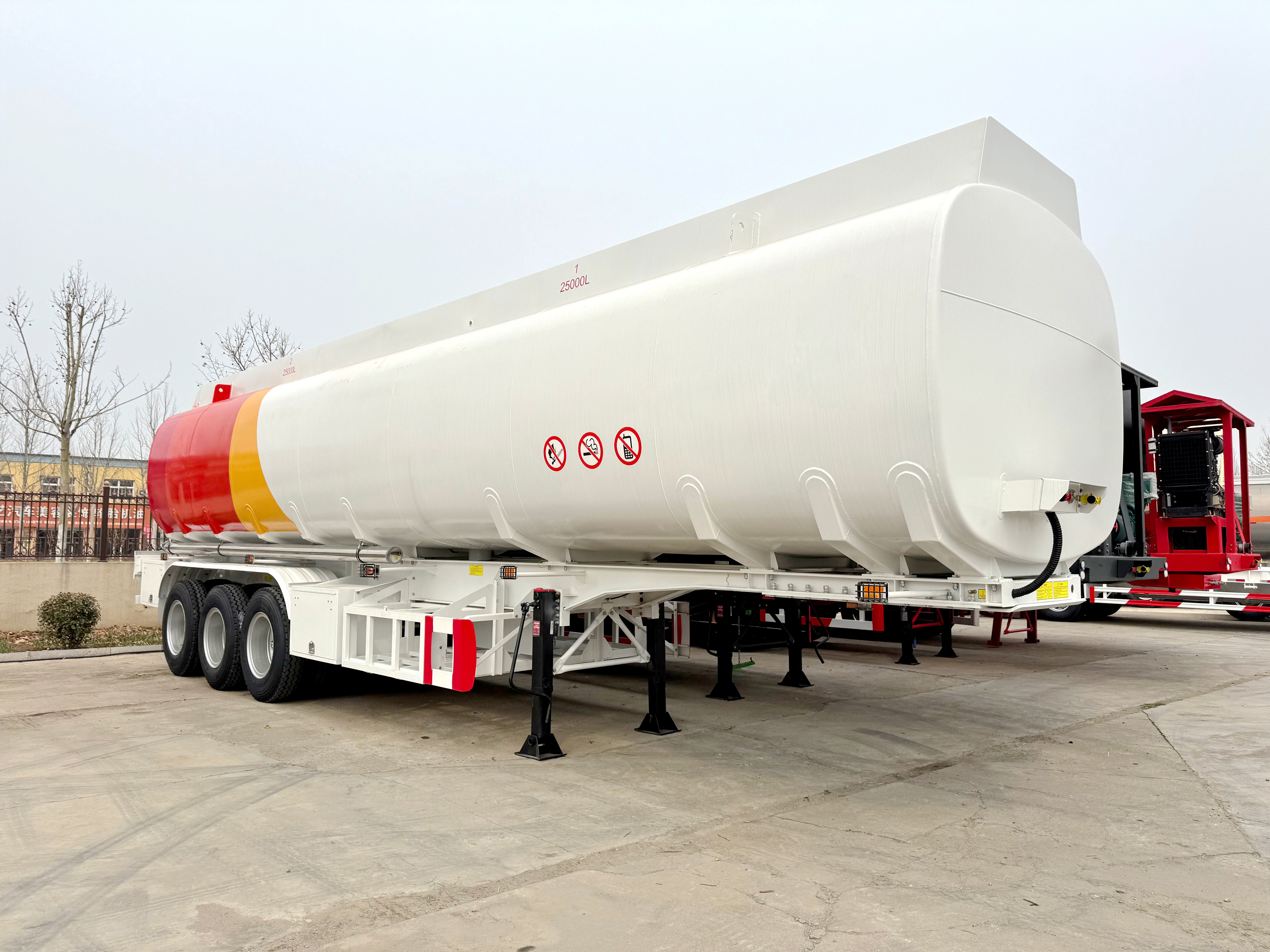
Flame arrestors act as the ultimate physical barrier for flammable materials. They do not use chemicals or water to extinguish a fire. Instead, they rely on fundamental thermodynamics and fluid mechanics to stop a flame front from propagating further into a system. They physically separate the ignition source from the main fuel volume.
The core mechanism relies on rapid heat dissipation. The critical component is the element, often constructed from crimped metal ribbon. Manufacturers take flat metal strips and corrugated strips, winding them together tightly around a central core. This creates thousands of uniform triangular passages. When a flame front hits this element, the matrix breaks the large flame into hundreds of microscopic flames. The massive surface area of the metal absorbs the thermal energy rapidly. This drops the temperature of the gas below its auto-ignition point, effectively quenching the flame before it can exit the opposite side of the matrix.
Engineers design these elements around the Maximum Experimental Safe Gap (MESG) and quenching diameter. The MESG determines the maximum gap size through which a specific gas flame cannot pass. Different chemical vapors require different gap sizes. Hydrogen requires a microscopic gap, while heavier hydrocarbon vapors allow for slightly larger passages. The physical process of quenching a flame follows a specific sequence:
Arrestors fall into two distinct categories based on flame speed and pressure dynamics. A deflagration moves at a few meters per second. Deflagration arrestors handle these subsonic flame propagations. They are best suited for end-of-line applications, such as atmospheric vents discharging directly to the atmosphere. They feature weather hoods to prevent rain ingress and sit at the very end of a vent pipe.
If a flame travels down a long pipe, the expanding hot gases push the unburned gas ahead of it, compressing it. This pre-compression accelerates the flame front. It transitions from deflagration to detonation, moving at supersonic speeds and generating massive pressure spikes. A standard deflagration arrestor will fail instantly under these conditions. You need a detonation arrestor. These units feature a much thicker element and robust flanged housings to absorb the kinetic shockwave and quench the supersonic flame. A stationary tank might utilize both types, while a mobile tanker trailer typically relies on specialized integrated venting systems designed for dynamic movement.
Safety compliance requires evaluating equipment through strict industry-standard lenses. Regulatory bodies continuously update guidelines based on new incident data, metallurgical advancements, and advanced risk modeling. API 2000 serves as the global benchmark for venting atmospheric and low-pressure storage tanks.
The shift from the 5th Edition (1998) to the 6th Edition introduced critical updates that changed how engineers design venting systems. The older guidelines offered more leniency regarding flame arrestor installation, often allowing open vents if the discharge velocity was high enough. The 6th Edition eliminated this loophole. It strictly requires flame arrestors for liquids with a flash point below 37.8 °C (100 °F). This change forces operators to proactively prevent ignition rather than relying solely on rapid venting to disperse the hazard.
This strict flash point threshold carries massive implications for operators handling mixed loads. If a fleet transports varying grades of crude oil, gasoline, and refined products, the equipment must meet the standards of the most volatile cargo. You cannot swap safety devices between loads. Therefore, the venting system must handle the lowest flash point product safely. API 2000 6th edition also incorporates the ISO 16852 testing standards, forcing engineers to specify arrestors based on exact gas groups (IIA, IIB, IIC).
Mobile regulations intersect heavily with stationary standards. While API 2000 governs stationary tanks, DOT and PHMSA regulations dictate the requirements for bulk liquid transportation on public highways. Mobile units face dynamic forces, including sloshing, severe vibration, and potential rollover scenarios. DOT 406 specifications mandate rollover protection. Vents must seal tightly if the trailer tips over to prevent massive spills. These mechanical seals must work in perfect harmony with the flame arrestor elements. The vapor recovery mandates also require in-line detonation arrestors to protect the trailer when connected to terminal loading racks, where a flash fire at the rack could travel back through the vapor hose into the trailer.
Procurement phases require careful evaluation of safety hardware. Buyers must weigh conceptual trade-offs to ensure both cost-effectiveness and strict compliance. You cannot simply look at the barrel capacity and axle count. The vapor control system dictates the operational safety and legal compliance of the entire unit.
When inspecting the spec sheet of a fuel tanker for sale, look closely at the venting systems. Modern units integrate pressure and vacuum relief valves directly with flame arrestors. You must evaluate the trade-off between vapor flow capacity and pressure drop. The dense metal matrix of an arrestor naturally restricts airflow. If the element is too restrictive, the tank could over-pressurize during high-speed loading at the terminal, or collapse under vacuum during rapid discharge. The engineering data must show that the arrestor can handle the maximum designed flow rate of the pump system without exceeding the safe working pressure of the tank shell.
Assess the hidden costs of older equipment. Buying a non-compliant trailer built to outdated API 2000 5th Edition standards might seem cheaper initially. However, retrofitting modern flame arrestors to meet current safety codes requires extensive engineering. You must cut into the tank shell, weld new flanges, perform non-destructive testing on the welds, and recertify the entire vessel. Factory-installed compliance always provides better long-term value and guaranteed integration.
Material compatibility determines the lifespan of the safety device. The arrestor matrix consists of very thin metal ribbons. If you transport corrosive cargo like sour crude, standard carbon steel will degrade rapidly. Corrosion destroys the precise gaps required to quench a flame, rendering the device useless. You must also watch for galvanic corrosion. If a carbon steel fitting connects to an aluminum tank shell without proper isolation gaskets, the aluminum acts as an anode and corrodes rapidly.
| Material Type | Corrosion Resistance | Best Application | Relative Cost |
|---|---|---|---|
| Carbon Steel | Low | Non-corrosive refined fuels (Diesel) | Low |
| 316L Stainless Steel | High | Standard crude, gasoline, mixed chemicals | Moderate |
| Hastelloy / Alloy C276 | Extreme | Highly sour crude, aggressive acids | High |
| Aluminum | Moderate | Weight-sensitive mobile applications | Moderate |
Factor maintenance accessibility into your evaluation. The ease of removing, cleaning, and inspecting the flame arrestor element matters immensely. If mechanics must dismantle half the top piping to reach the element, maintenance will get skipped. Look for swing-away housings or quick-release clamps that allow technicians to inspect the matrix without taking the trailer out of service for extended periods.
Safety devices introduce operational friction. While flame arrestors prevent explosions, they also create physical bottlenecks in the vapor path. Operators must implement strict risk mitigation strategies to maintain equipment integrity and ensure smooth daily operations.
Fouling and blockages represent the most common implementation risks in the field. Viscous fluids, crystallization, or particulate buildup can quickly clog the microscopic gaps in the arrestor matrix. When the matrix clogs, the tank cannot breathe. This leads to dangerous pressurization during thermal expansion or vacuum collapse during fluid extraction. Implementing differential pressure monitoring across the arrestor provides early warning signs of blockages. Strict preventive maintenance schedules remain the only reliable defense against fouling.
Cleaning requires removing the element from the housing. You cannot just blow compressed air through it while it sits on the trailer. Compressed air drives particulates deeper into the matrix, permanently clogging the passages. Technicians must use ultrasonic solvent baths to dissolve heavy crude residues or crystallized chemical deposits. After cleaning, they must perform a light test—holding the element up to a strong light source to verify all passages are clear.
Operator training dictates the success of loading and unloading protocols. High-flow transfer operations move thousands of gallons per minute. If an operator bypasses safety vents or improperly connects vapor recovery lines, the internal pressure will spike instantly. Training must emphasize the severe risks of tampering with venting hardware. Standard operating procedures (SOPs) must enforce rigorous pre-transfer inspections.
A: The 6th Edition shifted from the 5th Edition's leniency by utilizing updated risk models. It strictly requires flame arrestors for liquids with flash points below 37.8 °C (100 °F). This change emphasizes proactive ignition prevention rather than relying solely on rapid venting to clear flammable vapors.
A: Yes. The dense metal matrix restricts airflow, creating a natural pressure drop. If maintenance is neglected, particulates or viscous fluids can block the element. This blockage prevents the tank from breathing, leading to dangerous over-pressurization during loading or thermal expansion.
A: End-of-line arrestors handle subsonic deflagration and vent directly to the atmosphere at the end of a pipe. In-line arrestors integrate into closed piping networks and are often built to withstand supersonic detonation shockwaves caused by flames accelerating through long pipe runs.
A: Requirements depend entirely on the cargo's flash point, vapor pressure, and specific DOT/PHMSA regulations. Vehicles transporting highly volatile liquids like gasoline or crude oil require robust vapor control systems and flame arrestors, whereas those hauling non-flammable liquids do not.
A: Check the arrestor element for corrosion or particulate buildup. Verify that the pressure/vacuum valve seals remain intact. Ensure the system complies with current emission standards and confirm the hardware meets API 2000 6th Edition requirements for your specific cargo.
A: During an external fire, rapid cooling from suppression efforts or emergency pump-outs creates a vacuum inside the tank. The flame arrestor acts as a physical barrier, absorbing heat and preventing the external flames from being pulled through the vents into the vapor space.
A: Frequency depends entirely on the cargo's fouling tendencies. Viscous or crystallizing fluids require frequent cleaning. Operators should conduct routine visual inspections and utilize differential pressure checks to detect blockages early, scheduling ultrasonic cleaning before airflow becomes dangerously restricted.


