
Views: 0 Author: Site Editor Publish Time: 2026-08-25 Origin: Site


In high-volume construction and plant operations, material logistics dictate project timelines. Inefficient transport of bulk powders leads to site delays, material degradation, and inflated operational costs. Selecting a transport solution requires balancing payload capacity with strict bridge laws. You must ensure discharge systems handle abrasive materials without excessive residual waste, moisture contamination, or operator safety risks.
This guide provides a technical evaluation framework for selecting a dry bulk cement trailer. We analyze tank geometry, pneumatic system efficiency, safety integrations, and structural trade-offs to ensure optimal fleet investment and contamination-free transport.
Geometry Dictates Efficiency: The choice between a V shape cement tanker and multi-hopper designs directly impacts discharge speed, center of gravity, and residual material volume.
Pneumatic System Integration: A powder material tanker trailer relies on perfectly calibrated air compressors and fluidized beds; mismatched pressure systems lead to pipe blockages and extended unloading times.
Material and Weight Trade-offs: Selecting between high-strength steel and aluminum requires evaluating the trade-off between maximum payload capacity (tare weight) and long-term structural durability in abrasive environments.
Safety and Loading Protocols: Modern trailers must integrate robust top-loading safety features, including fall protection and pressure relief systems, to protect operators and maintain compliance.
The engineering behind a V shape cement tanker relies on gravity-assisted funneling. The tank slopes downward toward a single discharge point at the bottom center. This geometry matches the natural angle of repose for dry cement, which typically sits between 40 and 45 degrees. When the tank walls exceed this angle, material flows naturally toward the fluidized bed without requiring complex internal baffling. The steep angles prevent powder from bridging, rat-holing, or clinging to the interior walls during the unloading phase.
The single-hopper design allows for faster fluidization. Air concentrates in one primary chamber, aerating the cement rapidly. You do not have to balance air pressure across multiple chambers. This design also provides a lower center of gravity. The bulk of the material sits lower in the chassis between the axles. When you pull onto a muddy, rutted job site, that lower center of gravity keeps the rig upright and improves transit stability on uneven construction access roads. Residual cement remains minimal, often dropping below 0.3% of the total payload, which means you haul less dead weight on the return trip.
Fleet managers operating out of local batch plants prefer this design for its rapid turnaround times. The simplicity of the single discharge point reduces mechanical wear. You only have one primary discharge valve to maintain, one section of fluidized canvas to inspect, and a shorter run of discharge piping. This geometry excels in dedicated standard Portland cement transport on short-to-medium haul routes.
Cylindrical, multi-hopper designs serve higher volume requirements. Mechanics and drivers often call these W-shape trailers. These tanks feature two, three, or even four distinct hoppers integrated into a longer cylindrical shell. This structure maximizes the internal cubic capacity while remaining within legal vehicle length limits. The cylindrical shape provides inherent pressure vessel strength, distributing pneumatic stress evenly across the aluminum or steel shell.
Discharge mechanics in a multi-hopper setup require sequential unloading. Operators must manage valves for each hopper individually. This process demands a more complex pneumatic manifold system. Air flow must be directed to specific hoppers to maintain adequate fluidization pressure. If a driver opens multiple hoppers simultaneously, system pressure drops immediately, leading to severe pipeline blockages that require manual clearing.
To unload a multi-hopper trailer properly, operators follow a strict sequence:
Engage the air compressor and pressurize the main tank to exactly 0.2 MPa.
Open the fluidization valve for the front hopper to begin aerating the material.
Slowly open the front hopper discharge valve while monitoring the main pressure gauge.
Wait for the line to clear and the pressure to drop slightly, indicating the hopper is empty.
Close the front discharge valve and immediately open the fluidization valve for the next hopper in the sequence.
Repeat the process moving from front to back to maintain continuous fluidization and prevent line clogging.
You gain increased payload capacity for lighter materials with a W-shape design. However, this raises the center of gravity. Drivers must navigate highway curves and off-ramp loops cautiously. The sequential unloading process also results in longer unloading cycles compared to single-hopper designs, keeping the truck at the silo longer.
The bulk density of the target material dictates the required cubic capacity. Dense materials like standard Portland cement require less volume to hit maximum legal weight limits. A smaller, highly reinforced 30-cubic-meter tank serves this purpose perfectly. Conversely, hauling lighter powders requires a larger tank volume to achieve maximum payload profitability. If you put fly ash in a 30-cubic-meter tank, you will max out the volume long before you hit the legal weight limit, leaving money on the table every trip.
Material | Average Bulk Density (kg/m³) | Recommended Tank Volume | Tank Geometry Preference |
|---|---|---|---|
Portland Cement | 1,440 - 1,500 | 25m³ - 35m³ | V-Shape (Single Hopper) |
Fly Ash | 800 - 950 | 40m³ - 50m³ | W-Shape (Multi-Hopper) |
Lime Powder | 600 - 800 | 50m³ - 60m³ | W-Shape (Multi-Hopper) |
Frac Sand | 1,600 - 1,700 | 20m³ - 25m³ | V-Shape (Heavy Duty Steel) |
Structural requirements shift drastically when hauling alternative construction materials. Abrasive sand or soil stabilization powders demand thicker tank shells. Standard 4mm steel degrades quickly under the abrasive friction of frac sand. Upgrading to 5mm or 6mm high-tensile steel extends the asset's lifespan. The choice of tank thickness and geometry must align directly with the primary material hauled to prevent premature structural fatigue and costly mid-season weld repairs.
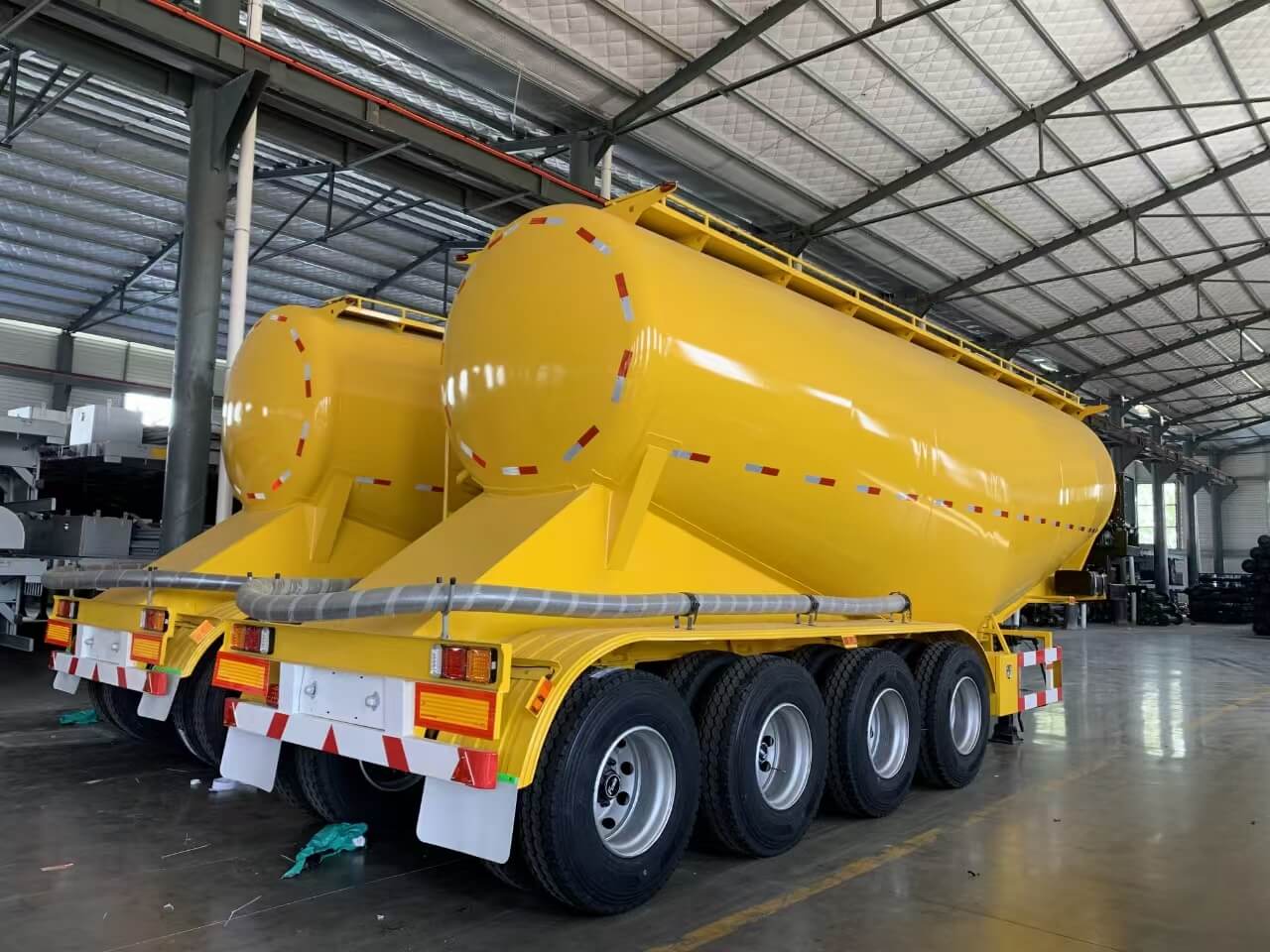
A powder material tanker trailer relies on a robust onboard air compressor to function. Without adequate air volume and pressure, the material remains a solid block. Technical specifications typically range from 12m³/min to 14m³/min capacities. Single-hopper trailers generally operate efficiently with a 12m³/min unit. Multi-hopper configurations require 14m³/min or higher to maintain pressure across complex manifolds and longer piping runs. The compressor must deliver clean, dry air. Any moisture introduced by the compressor will cause material hydration inside the tank.
Power delivery methods vary based on fleet setup. Power Take-Off (PTO) systems utilize the tractor's transmission to drive the compressor. Independent diesel engine setups mount directly on the trailer chassis, usually near the landing gear.
Power Delivery Method | Weight Impact | Operational Flexibility | Maintenance Requirements |
|---|---|---|---|
Tractor-Mounted PTO | Lightest (Reduces tare weight) | Low (Trailer must stay attached to specific tractor) | Requires tractor transmission servicing and driveline checks |
Trailer-Mounted Diesel | Heavy (Adds engine and fuel tank weight) | High (Drop-and-hook capable, unloads with any tractor) | Requires separate oil changes, fuel filters, and engine maintenance |
Operating pressure ranges sit strictly around 0.2 MPa (approximately 29 PSI). Maintaining this pressure ensures continuous material flow. Dropping below this threshold causes the fluidized material to settle, instantly blocking the discharge pipe. Exceeding this pressure risks rupturing internal seals, tearing the fluidized bed canvas, or triggering the automated safety valves, which violently vent the excess pressure and cover the immediate area in cement dust.
The internal fluidized bed is the heart of the pneumatic unloading process. Positioned at the bottom of the hopper, it consists of a permeable canvas or synthetic mesh stretched over a metal frame. Air from the compressor forces its way up through this mesh. This aeration process separates the cement particles, reducing friction. The dry powder transitions into a liquid-like flow state, allowing it to move smoothly toward the discharge valve.
Discharge pipelines require specific engineering to handle abrasive flow. The standard diameter is 4 inches, balancing flow rate with pressure maintenance. These pipes utilize wear-resistant steel alloys. The elbows and bends experience the highest friction. Material slams into these curves at high velocity. Manufacturers reinforce these sections with thicker steel or replaceable wear plates. Smooth internal welds prevent material turbulence and localized wear spots that would otherwise blow out after a few months of heavy use.
The mechanics of the blow-down valve and check valves protect the pneumatic system. Check valves sit between the compressor and the tank. They prevent pressurized cement dust from flowing backward into the compressor during shutdown. If a check valve fails, cement dust enters the compressor housing, destroying the rotors. The blow-down valve allows operators to safely depressurize the tank after unloading. You must open this valve before opening any manholes to prepare the vessel for transit.
Top-loading procedures occur via sealed manholes on the roof of the tank. Operators must access these ports at batch plants or silos, often climbing up the rear ladder in less-than-ideal weather conditions. The safety infrastructure required includes non-slip aluminum walkways and collapsible handrails. These handrails deploy pneumatically or manually, creating a secure perimeter around the manholes. Integrated fall protection systems tie-off points are mandatory to protect operators working at height.
Automated pressure relief valves function as the primary fail-safe. These safety valves prevent catastrophic tank over-pressurization. During the loading phase, displaced air must escape. During pneumatic unloading, compressor surges can spike internal pressure rapidly. The safety valves automatically vent excess air if the internal pressure exceeds the 0.2 MPa threshold. Mechanics must test these valves regularly; a seized safety valve turns the trailer into a bomb.
Axle placement directly impacts legal payload limits. Regional bridge laws and weight restrictions dictate maximum allowable gross vehicle weights based on the distance between axle groups. Tandem axles suit standard loads in regions with lenient weight laws. Tri-axle or quad-axle setups distribute the gross weight over a larger footprint. This configuration allows fleets to maximize their payload legally, reducing the total number of trips required for large construction projects.
Suspension systems protect the tank during transit. Air ride suspensions absorb road shock effectively. They protect the rigid tank shell from torsional stress, especially when navigating off-road construction sites. Mechanical leaf spring suspensions offer rugged durability and lower upfront costs. However, they transfer more vibration to the tank. Over years of heavy use, this constant vibration accelerates weld fatigue, leading to hairline cracks in the pressure vessel.
Industry-standard discharge rates range from 1.2 to 1.5 tons per minute. High-efficiency systems can push this closer to 1.7 tons per minute under optimal conditions. This metric directly impacts turnaround times at the batch plant. Faster unloading means more trips per shift. The efficiency relies on the precise match between the compressor output, the fluidized bed condition, and the receiving silo's venting capacity. If the silo cannot vent air fast enough, backpressure builds, and the discharge rate plummets regardless of the trailer's capabilities.
The financial impact of residual volume is substantial. Acceptable limits are typically less than 0.3% of the total payload. Excess leftover material acts as dead weight. It reduces subsequent payload capacities, directly impacting operational efficiency. High residual volumes also require manual cleanout. Operators must depressurize the tank, open the manholes, climb inside with a shovel, and manually push the remaining powder toward the discharge valve. This exposes operators to confined space risks and delays fleet schedules.
Evaluating materials requires comparing high-yield carbon steel with aluminum alloys. High-yield carbon steel is cost-effective and highly durable. It withstands the abrasive nature of sand and rough off-road environments. However, it carries a heavier tare weight. Aluminum alloys command a premium cost but significantly reduce tare weight. This maximizes the legal payload per trip. Aluminum requires specialized welding for repairs and is generally reserved for non-abrasive powders.
Material Type | Tare Weight Impact | Abrasion Resistance | Repairability | Ideal Application |
|---|---|---|---|---|
High-Yield Carbon Steel | Heavier (Reduces max payload) | Excellent | Standard welding techniques | Abrasive sand, rough terrain, mixed materials |
Aluminum Alloy | Lighter (Maximizes payload) | Moderate to Low | Requires specialized TIG welding | Dedicated cement, long-haul highway routes |
Stainless Steel | Heavy | High | Specialized welding | Corrosive materials, food-grade powders |
The critical risk in dry bulk transport is moisture ingress. When water enters the tank, it causes cement hydration. The powder clumps and hardens inside the hopper. This destroys the payload and requires extensive, labor-intensive chipping with pneumatic hammers to remove the hardened concrete from the tank walls and fluidized bed. A single rainstorm leaking through a bad seal can cost thousands of dollars in damage and downtime.
Strict inspection protocols prevent this. Operators must inspect manhole covers and rubber gaskets daily. A simple chalk test can verify the seal's integrity: rub chalk on the manhole rim, close the lid, open it, and check for a solid chalk line on the rubber gasket. Pressure relief valves must seat perfectly after venting. Any worn gaskets must be replaced immediately to ensure a hermetic seal during transit and outdoor storage.
Cross-contamination risks arise when utilizing the same trailer for different materials. Switching between Portland cement, fly ash, and soil stabilization powders requires rigorous protocols. Trace amounts of fly ash can alter the chemical properties of a subsequent cement load, leading to rejected batches at the construction site. You cannot simply blow the tank empty and load a different chemical powder.
Best practices demand complete pneumatic cleanouts. Operators must follow a strict procedure:
Run the compressor at full capacity to purge the main lines.
Open and close the blow-down valves rapidly to shake loose any clinging material.
Depressurize the tank completely and open all manholes.
Perform an interior washdown using high-pressure water for sensitive or reactive materials.
Run the air compressor for at least an hour to completely dry the interior.
Verify zero moisture remains in the fluidized bed canvas before loading the next batch.
The maintenance lifecycle of the fluidized bed canvas requires close monitoring. The canvas degrades over time due to constant friction and air pressure. As the pores clog with ultra-fine dust or tear from abrasive particles, aeration efficiency drops. Unloading times increase, and residual volume spikes. Fleet managers should schedule canvas inspections quarterly. Mechanics must replace the mesh at the first sign of widespread fraying or hard spots where moisture has caused localized cement hardening.
Routine servicing requirements for the air compressor are non-negotiable. Dusty construction environments choke air filters rapidly. Air filter replacement must occur based on operating hours, not just mileage. Oil monitoring is critical for PTO and diesel compressors alike. Contaminated oil leads to compressor overheating. An overheating compressor can force oil vapor into the air lines, which then coats the inside of the tank and ruins the cement payload.
Mitigation of pipeline blockages requires strict procedural adherence. Blockages usually occur due to sudden pressure drops, opening valves too quickly, or wet material in the silo pipe. Proper depressurization and cleanout procedures post-discharge prevent material from settling in the lower elbows. Operators must ensure the discharge pipe is completely clear before closing the valves, disconnecting the hose, and moving the vehicle.
Take the following steps to optimize your fleet selection and ensure operational readiness:
Audit your current batch plant unloading infrastructure to ensure compatibility with standard 4-inch discharge pipelines and 0.2 MPa pressure systems.
Calculate legal payload limits for your primary routes to determine whether a tandem, tri-axle, or quad-axle configuration maximizes your operational efficiency.
Request technical spec sheets from shortlisted manufacturers, focusing strictly on certified discharge rates, residual volume percentages, and safety integrations.
Verify that the onboard compressor ratings match the specific bulk density and fluidization requirements of your primary materials.
Establish a strict preventative maintenance schedule for manhole gaskets, check valves, and fluidized bed canvases before deploying the new asset.
A: Capacities typically range from 25 cubic meters to over 60 cubic meters. Because standard cement is highly dense, a 30 to 40 cubic meter tank is usually sufficient to reach the maximum legal gross vehicle weight. Lighter bulk powders require the larger 60 cubic meter tanks to maximize payload.
A: The unloading process relies on pneumatic pressure. An onboard air compressor pressurizes the tank. The air passes upward through a fluidized bed at the bottom of the hopper, aerating the dry powder. This creates a liquid-like state, and the internal pressure forces the material out through the discharge pipe.
A: The V-shape design features a lower center of gravity and a single discharge point. This geometry allows for faster fluidization, superior transit stability on rough roads, and significantly less residual material left in the tank. It is highly efficient for dense powders like standard cement.
A: Yes, they are versatile. However, hauling highly abrasive materials like sand requires thicker steel tank shells and specialized wear-resistant piping. Switching between different materials also requires rigorous pneumatic cleanouts and washdowns to prevent cross-contamination.
A: Top-loading requires operators to work at height. Mandatory safety features include top-walkway fall protection, such as collapsible pneumatic handrails, and non-slip aluminum grating. Properly calibrated pressure relief valves are also required to protect operators from catastrophic tank over-pressurization.
A: The standard operating pressure is typically around 0.2 MPa (approximately 29 PSI). Maintaining this pressure ensures smooth material flow. Exceeding this limit risks damaging the internal tank seals, blowing the safety valves, or over-pressurizing the receiving silo at the batch plant.
A: You prevent moisture ingress by maintaining intact manhole gaskets and performing regular chalk tests on the seals. You must also ensure the air compressor's intake filters remain dry and keep all discharge and blow-down valves fully sealed during transit and outdoor storage.


